- Authors

- Name
- Desi Ilieva
Next Article
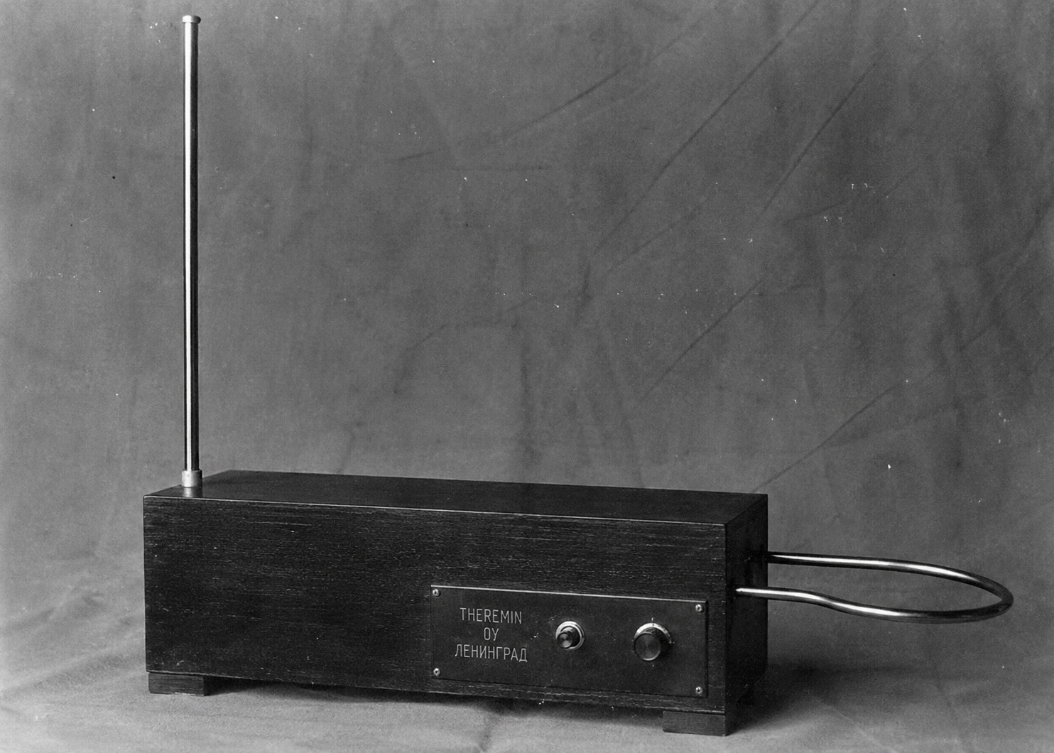
The theremin is the only musical instrument played without physical contact. You move your hands through the air and sound comes out. That's not magic — it's capacitance, oscillators, and a neat bit of analog signal processing invented in 1920.
- A Brief History
- The Two Antennas
- The Oscillator Circuit
- Volume Control
- The Signal Chain
- Playing It
- Prototyping One
- Summary
A Brief History
Léon Theremin was a Russian physicist working on proximity sensors in 1920 when he noticed that his body affected the pitch of an oscillator circuit as he moved near it. He turned that observation into an instrument, demonstrated it to Lenin, toured Europe, moved to the United States, and patented it in 1928.
The theremin showed up early in film scores — Spellbound (1945), The Day the Earth Stood Still (1951) — because that wavering, continuous pitch was unlike anything else. It's been used in classical performance, psychedelic rock, and experimental music ever since.
What makes it interesting from an engineering perspective is that the human body is part of the circuit. You're not pressing keys or moving strings — you're acting as a variable capacitor.
The Two Antennas
A theremin has two antennas with different jobs:
- Vertical antenna (right hand) — a straight metal rod, usually on the right side. Controls pitch. Moving your hand closer raises the pitch, moving away lowers it.
- Horizontal antenna (left hand) — a metal loop, usually on the left side. Controls volume. Moving your hand closer to it reduces volume down to silence.
Both work on the same physical principle: your hand and the antenna form a capacitor. The human body, being conductive and grounded through the floor, acts as one plate. The antenna is the other. The air gap between them is the dielectric. As you move your hand, the distance changes, and so does the capacitance.
C ≈ ε₀ * A / d
Capacitance increases as distance d decreases. This change in capacitance is what the circuit detects and converts into pitch and volume control.
The Oscillator Circuit
The pitch side of a theremin uses two oscillators — this is called heterodyning, or a beat frequency oscillator (BFO).
Oscillator 1 runs at a fixed frequency — typically somewhere around 170–500 kHz, well above the audio range. It's reference-only and never changes.
Oscillator 2 is variable. Its frequency is set by an LC circuit — an inductor and a capacitor in a resonant loop. The antenna is wired in parallel with the capacitor:
f = 1 / (2π * √(L * C))
When your hand approaches the antenna, capacitance increases, which lowers the resonant frequency of oscillator 2. When you move away, capacitance decreases and the frequency rises.
The audio output is the difference between the two oscillator frequencies. If oscillator 1 runs at 170 000 Hz and oscillator 2 runs at 170 440 Hz, the beat frequency is 440 Hz — an A4. Move your hand slightly and that difference shifts by a few Hz, which you hear as a pitch change.
f_audio = |f_fixed - f_variable|
This is why thereminists work in a very specific region of space around the instrument. Too close and the frequencies converge toward zero. Too far and the difference exceeds the audible range.
Volume Control
The horizontal loop antenna works the same way physically — hand proximity changes capacitance — but instead of feeding into a heterodyne pair, it connects to a variable gain amplifier (VGA) that controls output level.
As your hand approaches the loop, the capacitance change detunes a separate oscillator, which drives the gain control of the VGA down toward silence. Moving away opens it back up. The result is a left-hand volume control with no mechanical parts and no touching anything.
The Signal Chain
Putting it together, the signal path from oscillators to speaker is:
Pitch antenna
  → changes C in LC circuit
  → shifts f_variable
  → mixer computes |f_fixed - f_variable|
  → audio frequency out

Volume antenna
  → changes C in separate circuit
  → VGA gain control
  → shapes amplitude of audio signal

Audio signal → amplifier → speaker
In original 1920s theremin circuits everything was vacuum tubes. Modern designs use op-amps, analog multipliers, and CMOS oscillator ICs instead — the principle is identical, the components are just smaller and more stable.
Playing It
The theremin has no frets, keys, or stops. Every pitch exists in a continuous field around the right antenna. This makes it one of the hardest instruments to play in tune — there's no physical feedback telling you where a note is.
Skilled thereminists like Clara Rockmore (who worked with Léon Theremin directly) developed precise muscle memory for hand positions. Modern players use the same approach — you internalise the spatial map of the instrument over time.
The continuous pitch control also makes vibrato, portamento, and glissando natural and effortless. The tone is inherently legato because there's no articulation mechanism — notes always flow into each other unless the left hand closes the volume down.
Prototyping One
A basic theremin prototype doesn't need much. The simplest version uses two CMOS oscillator circuits — a common approach uses the IC 74HC14 (hex Schmitt trigger inverter) or a 555 timer to build each oscillator.
What you need:
- 2× CMOS oscillator circuits (555 timers or 74HC14)
- Inductors — around 1–10 mH depending on your target frequency
- Capacitors for the LC tanks
- A metal rod antenna (plain copper wire works)
- An analog mixer or op-amp difference stage
- Audio amplifier and speaker or headphone jack
Basic pitch oscillator:
// Conceptual — component values depend on your L and target freq range
// LC oscillator tuned to ~200 kHz
// Antenna wire connected in parallel with tank capacitor

// Fixed oscillator: L=2.2mH, C=330pF → f ≈ 186 kHz
// Variable oscillator: same L, C=270pF + C_hand_antenna
//   hand proximity adds ~1-30pF → shifts f by a few hundred Hz
The two oscillator outputs feed into a mixer — in the simplest case, just summing them through a diode detector or a multiplier IC. The high-frequency carrier components cancel or filter out, and what remains in the audio range is the beat frequency.
A low-pass filter after the mixer removes the high-frequency residue and passes only the audible difference tone.
For volume control, a third oscillator drives a LED/LDR opto-isolator (an old but very usable approach) whose resistance controls the gain of the output stage. Alternatively, a proper VCA IC gives you cleaner control.
An Arduino-based theremin is also possible but works differently — you'd use pulseIn() to measure oscillator period, compute the frequency difference in code, and drive a DAC or PWM output. It's a good starting point for understanding the concept but real thereminists notice the stepped pitch resolution.
The analog approach, even a rough prototype on breadboard, produces a continuous pitch that responds the same way a real theremin does. Start there.
Summary
The theremin works by treating your body as a variable capacitor in an LC oscillator circuit:
- Two antennas — vertical rod for pitch, horizontal loop for volume — both detect hand proximity as a change in capacitance
- Heterodyning — two oscillators running near the same frequency, the audible output is the difference between them
|f_fixed - f_variable| - LC oscillator — frequency set by
f = 1 / (2π√LC), the antenna is in parallel with the tank capacitor, hand proximity shiftsCand thereforef - Volume control — a separate antenna drives a VGA, closing volume as the hand approaches the loop
- Signal chain — oscillator pair → mixer → low-pass filter → VGA → amplifier → speaker
- Prototyping — two CMOS or 555 oscillators, an LC tank per antenna, a mixer stage, a low-pass filter, a VGA for volume; breadboard-level builds work fine for learning the concept
- Continuous pitch with no physical reference is what makes it hard to play and interesting to build